In this version plate solving is supported by visual pin point engine. You should install it and GSC catalog on your PC. These installation are not part of Polypus installation. After that in the configuration dialog in the "Plate solving" page you can enable the Pin point engine use, select folder where GSC catalog is and set the frame expansion (in percentage) used for star searching.
Friday, March 15, 2024
Polypus 2.07 supports plate solving
Friday, March 1, 2024
Polypus 2.06 support multiconfiguration and up to 5 instruments
Whit the versione 2.6 Polypus support more then one configuration. Each configuration is saved in xml file in the folder |Documents\Polypus2\Configuration. In this way is easy move a configuration between PCs. In the first configuration page it is possbile create configurations and select the current one
Thursday, October 12, 2023
Sunday, January 30, 2022
Now Polypus2 supports scripts
Whit the version 2.02 the script support is introduced.
Script support is finalized to a full automatic observation session even without people in the observatory
The first change you can find is in the menu. Now an additional ribbon menu named "Automatic" allows you to select and edit three different task script. One for each specific purpose.
Observation task script: where you can put all the observation activities
Time task script: where you can put activites you needs where a defined time (e.g decondense)
Closure task script: where you can put activities for observatory closure and final activities like fla, dark
Second big change is a specifi page able to edit and run scripts.
On the right you find the syntax colored editor for script writing. Using these element you can work off line loading, editing and saving every scripts. During editing syntax color allows you to see immediatly possibile syntax error.
On the left element you see the task list in execution with their state and the current executed script where current line is highlighed. On the side you can check the current state of script variables
Tuesday, November 16, 2021
Polypus 2.01 version ready
The second useful version of Polypus is ready, version 2.01.
you can find it in resources
Photo menu is updated so to manage three cameras: for photo, for PEC and for spectroscope.
Wednesday, July 14, 2021
Polypus 2.00 version ready
The first useful version of Polypus is ready, version 2.00.
you can find it in resources
Now the camera management is implemented so photos can be taken. A new menu bar is present where you can select exposure and binning, assign name to the object. After that you can run a shot.
Sunday, May 23, 2021
Polypus2 Objects
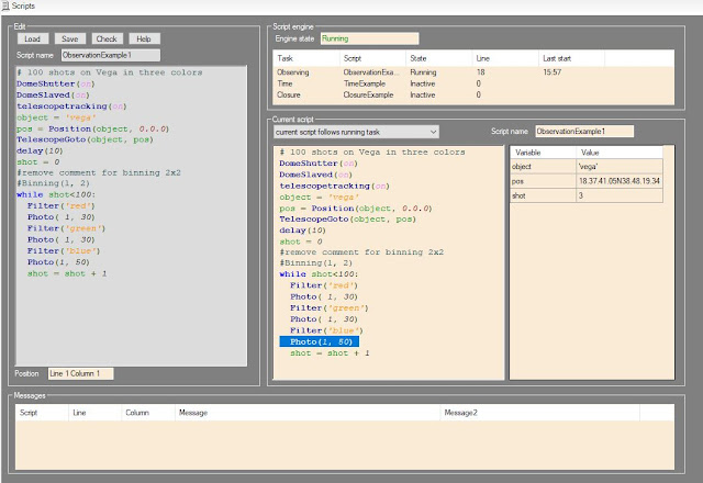
I come to you after days with the second beta of Polypus2 software. You can download it from resources. In this time I have implemented the object view. This is activated by the command in the view menu. Here you can select the ephemerid epoch and, in case of near object, show the topocentric coordinates.
In the object view it is possibile see some object lists:
- Favorites
- sync stars
- Planets
- Asteroids
- Messier
- NGC
- UGC
For selected object is showed the position in the sky, the sky chart centered where object is using GSC catalog. Some additinal information are shoed. when object is over the horizon it is possible command a telescope goto on it. Objects can be inserted in the favorites list.
Sync stars list contains 20 bight starts with low declination along all right ascensions. This allow you a precise telescope sync. Star position takes in count the proper motion
Planet list contains all solar system planet plus Sun and Moon.
Sun and Moon positions are computed using formulas from “Astronomia con il computer” by Janes Meeus.Mercury to Neptune positions are computed using VSPO theory.
Mercury to Neptune magnitude are computed using formulas from “Computing Apparent Planetary Magnitudes for The Astronomical Almanac” by James L. Hilton US Naval Observatory
Asteroid list shows the position of object in MPCORB.DAT from Minor Planet Center, positions are computed using formulas from “Astronomia con il computer” by Janes Meeus.
Using the tab sheet Altitude is it possibile see the observation condition of the object in current (or selected) night. On horizontal axis you have the local time on vertical axis the object altitude. Yellow backgroung are for day light, blu background for twilight and dark for astronomical night. Red line show you the object altitude. Because the moon can often annoy astronomical observations it is possible show also the moon altitude by a green line.
Friday, April 9, 2021
Polypus 2 developing
Hello,
now the controller and driver part of the project is finished so the third step need to be started. It is the step requiring the most effort. The develop of a new version for the software managing the entire observatory. Since 2010 in the Bassano Bresciano observatory we use Polypus a software we build for this purpose with CBuilder compiler in C++. Now we need a new version of this software able to manage more devices. At this point Ascom Drivers are mandatory in order to don’t have Polypus strictly link the current device we use now. Polypus 2 will be developed by VisualStudio in C#.
Polypus 2 should support window docking so it should be possible dock windows in the program where you prefer. This is not a native Visual studio feature. After an investigation and test we select this open source library
https://www.codeproject.com/Articles/42800/Visual-Studio-IDE-like-Dock-Container-Second-Versi
https://www.codeproject.com/Articles/25907/A-Professional-Ribbon-You-Will-Use-Now-with-orb
Program should use dark color so to be useful the observatory light and to be style updated. Icons should be monochromatic black.
Here is the prototype of the main window
when a first version where the manual movement are working I'll publish it
Saturday, March 20, 2021
Driver ASCOM for dome, focusers and switch
Now I have developed all the others drivers for object controlled by Raspberry application. They are: dome, focuser1, focuser2, focuser3 and switch. All driver was checked with conformance checker and conformance document was generated.
Also in this case communication between driver and Raspberry is done via TCP/IP, using other ports.
For these reason the Rapberry application was update, now its version is 1.2.0.0. In the resource is presente the new version.
You can find all new drivers and conformance documents in the resource.
Dome driver supports these features:
Slaved
Home finding
park
Open/close shutter
Absolute position
Maxposition and step configurable in Raspberry application
Ready only analogue value with temperature in the dome
Read/write boolean value for flat field light
Read/write boolean value for telescope decondence fan
Wednesday, March 10, 2021
Driver ASCOM for telescope
Because of Raspberry controller is able to manage different devices more Ascom driver are needed, one for each device. Now the first driver is developed using Microsoft Visual Studio, thanks to development tools supplied by Ascom Platform. Conformance checker was used to verify and validate it. Conformance document was generated.
Communication between driver and Raspberry is done via TCP/IP, Each driver
uses its own port. Raspberry implement a UDP broadcast communication used to
make know its IP address to the driver, in this way IP address can be discovered
during the driver setup.
These are the supported
features:
- Alignment: Polar
- Sync and async
target and coordinate Slewing
- Target and
coordinate Sync
- Tracking: Sireal with
the possibility set right ascension and declination rate
- Move axis support
- Topocentric equatorial
system
- Parking on local
meridian at declination 0
- Pulse guide
support
- Aperture area and
diameter and focal length are from Raspberry controller where can be
configured.
- Observatory site
location is from Raspberry controller where can be configured.
Saturday, February 20, 2021
Application Raspberry
First software version for Raspberry is ready.
Using Codesys 3.5SP16 and Softmotion 4.8.0.0 an application was developed
able to manage in the correct way all devices. This first version is marked
1.0.0.0.
In this version all the user activities are done through web page visible using a browser connected to the controller IP address (http://192.168.3.100:8080/webvisu.htm). Address is assigned to controller by DHCP so can be different.
In the resource: Codesys application for Raspberry you can find the zip file with this software
Home page shows software information and allow the observatory position
set up
Telescope page allow the axis control. You can sync or move axis on a
position or with drift velocity. It is possibile set the maximum speed and
acceleration but for each movement you can have different speed from 0 to maximum.
Dome page shows:
·
States of push buttons and commands for dome motors.
·
Dome position as encoder pulse and azimut.
·
Azimut position for home (home input sensor) and park.
·
Shutters condition and timers
·
Temperature in the dome
Focuses page shows for each focuser:
- Current and target position
- Working and motor enable
condition
- Backlash setting.
Application is deployed on more task with different priority and interval time.
- Ethercat task run
in highest priority (0) every 4 milliseconds. It generates the position
setpoint for both motor and send the Ethercat frame.
- Main task run in medium
priority (16) every 20 milliseconds. It manages: State machine for
software startup, all digital I/Os directly managed by Raspberry and dome.
- Slow task run in
low priority (20) every 10 milliseconds. It manages all I2C devices: digital
out for focuses, analog input for temperature reading and FRam read/write.
- Visu task in lowest priority (31). It
manages the visualization of web pages.
Features
In the FRam are saved two different kind of information:
- Configuration
data. Data related to the specific use in your own observatory: observatory
location, motor speed and acceleration for axis, dome encoder, focuser Backlash.
These data are showed in orange in the page. A button allows the change
saving in FRam.
- Application data.
Data relating to the current position of motors, dome, shutters, focusers.
These data are saving automatically every second and restored at next
power up. At power current telescope right ascension is computed so it
should be possible do a goto command without a sync.
Telescope declination axis can be:
- Synched to a
specific position.
- Moved with a smooth
velocity profile to a target position.
- continuously moved
at low speed (drift) in order to follow object with proper motion (e.g.,
comet)
Telescope right ascension axis has the same possibility of declination plus
the possibility to activate the tracking. Right ascension is correctly computed
both with tracking on and off.
Dome can rotate both manually and automatically (slaved). Shutters can be
open and close both manually and automatically. There are six buttons for dome/shutters
management:
- Dome right
- Dome left.
- Sliding open
- Sliding close
- Tilting open
- Tilting close,
When they are pushed alone, they activated manually the function as their
name. When push is removed motion is stopped.
Pushing dome buttons together dome enter in “slaved” state so is following
automatically the telescope azimuth.
A “double click” on dome right button activates the automatic positioning
on home position.
A “double click” on dome left button activate the automatic positioning on park
position.
Pushing sliding buttons together it is activated the automatic shutters
opening.
Pushing tilting buttons together it is activated the automatic shutters closing.
Focuser step motors are activated when the target position is different
than the current position. Motors are driven with fixed frequency 100hz in
start-stop way. It is possible define a forward or backward backlash
compensation.
Tuesday, February 9, 2021
Hardware ready software in progress
I have mounted Raspberry board, I/Os boards and rele board an plastic supports. These was arranged with DIN rail hangs so they are finnaly mounted on two DIN rail.
Now DIN rail are placed on a wood support in order to have an easy equipment for testing. In the final deployment they will be placed in the observatory frame.
Now is only matter of software.
Tuesday, January 12, 2021
Step motor board
Hello to all,
In the time from last post I have designed an realized the board for step motor driving.
Three step motors need to be driver by the controller in order to act as focuser. For step motor adapting an L298 bridge is chosen. From the market is possible found chip board with this component and radiator.
Every board need 5 digital output for driving: Enable, IN1 (A phase +), IN2 (A phase -), IN3 (B phase +), IN4 (B phase -). It is not mandatory have the possibility to move all focus at the same time so phase signal can be common for all motor having maintaining one enable signal for each motor. In this way 3 enable signal plus 4 phase signal are needed.
No more digital output are available directly on raspberry board so the solution for increase its number is the use of a little board with the component PCF8574. It is a remote 8-Bit I/O Expander for I2C Bus
Because of step motor power signal can generate noise in the low power CPU
signal is a good solution make outputs optoisolated.
This is the board schematic available also as external file
Thursday, December 17, 2020
IO Baord
Raspberry has 17 GPIO pins able to be programmed as input or output so these can be used as digital I/Os. They manage segnals with few Volts with the same electric potential of Raspberry, it is not a good idea have a long wiring with these signals, the risk is for the incoming noise and electric spike, they could hung up the Raspberry CPU.
For this purpose an expansion board need to be developed where 8 digital signal 24Vcc are optoisolated and adapted to the Raspberry GPIOs voltage and 8 Raspberry digital outputs drives relès. Relés make outputs optoisolated so driven signals can go far way from Raspberry.
For each digital input a this circuit is implemented
For digital output we bought a board from the market suitable for interfacing with Raspberry. Unfortunately this board reveses the commands from Raspberry, this not acceptable because during the Raspberry boot up for a litte time all reles are on. For this reason on the board an 8 inverter ports (74LS240) is applied in order to have the correct driving condition.
An analog input is needed in order to get the current observatory temperature. We bought an I2C analog to digital converter ADS1015. This is able to get 4 single ended signal or 2 differential signal. We select the second option in order to connect one PT100 termoresistor, this assure e low noise signal. This is the only not optioisalted signal so ti can’t go much far away from controller. A trimmable resistance che adjust the current flowing in the PT100 so to have precise measure.
An I2C FRam memory is mounted allowing the controller to save information need to be retained when power down. It has 32Kbyte more than enough.
In the resource the full board schematic is available


