Saturday, February 20, 2021

Application Raspberry

 First software version for Raspberry is ready. 

Using Codesys 3.5SP16 and Softmotion 4.8.0.0 an application was developed able to manage in the correct way all devices. This first version is marked 1.0.0.0.

In this version all the user activities are done through web page visible using a browser connected to the controller IP address (http://192.168.3.100:8080/webvisu.htm). Address is assigned to controller by DHCP so can be different.

In the resource: Codesys application for Raspberry you can find the zip file with this software


Home page shows software information and allow the observatory position set up


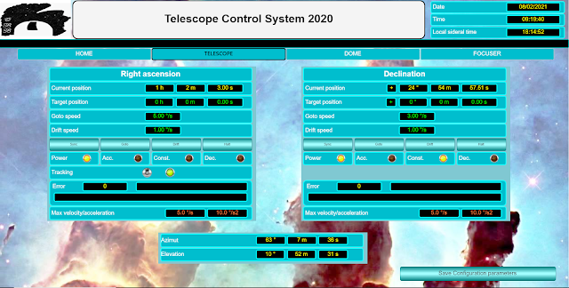
Telescope page allow the axis control. You can sync or move axis on a position or with drift velocity. It is possibile set the maximum speed and acceleration but for each movement you can have different speed from 0 to maximum.


Dome page shows:

·         States of push buttons and commands for dome motors.

·         Dome position as encoder pulse and azimut.

·         Azimut position for home (home input sensor) and park.

·         Shutters condition and timers

·         Temperature in the dome


Focuses page shows for each focuser:

  • Current and target position
  • Working and motor enable condition
  • Backlash setting.


Application is deployed on more task with different priority and interval time.


  • Ethercat task run in highest priority (0) every 4 milliseconds. It generates the position setpoint for both motor and send the Ethercat frame.
  • Main task run in medium priority (16) every 20 milliseconds. It manages: State machine for software startup, all digital I/Os directly managed by Raspberry and dome.
  • Slow task run in low priority (20) every 10 milliseconds. It manages all I2C devices: digital out for focuses, analog input for temperature reading and FRam read/write.
  •  Visu task in lowest priority (31). It manages the visualization of web pages.

 Features

In the FRam are saved two different kind of information:

  • Configuration data. Data related to the specific use in your own observatory: observatory location, motor speed and acceleration for axis, dome encoder, focuser Backlash. These data are showed in orange in the page. A button allows the change saving in FRam.
  • Application data. Data relating to the current position of motors, dome, shutters, focusers. These data are saving automatically every second and restored at next power up. At power current telescope right ascension is computed so it should be possible do a goto command without a sync.


Telescope declination axis can be:

  • Synched to a specific position.
  • Moved with a smooth velocity profile to a target position.
  • continuously moved at low speed (drift) in order to follow object with proper motion (e.g., comet)

Telescope right ascension axis has the same possibility of declination plus the possibility to activate the tracking. Right ascension is correctly computed both with tracking on and off.


Dome can rotate both manually and automatically (slaved). Shutters can be open and close both manually and automatically. There are six buttons for dome/shutters management:

  1. Dome right
  2. Dome left.
  3. Sliding open
  4. Sliding close
  5. Tilting open
  6. Tilting close,

When they are pushed alone, they activated manually the function as their name. When push is removed motion is stopped.

Pushing dome buttons together dome enter in “slaved” state so is following automatically the telescope azimuth.

A “double click” on dome right button activates the automatic positioning on home position.

A “double click” on dome left button activate the automatic positioning on park position.

Pushing sliding buttons together it is activated the automatic shutters opening.

Pushing tilting buttons together it is activated the automatic shutters closing.


Focuser step motors are activated when the target position is different than the current position. Motors are driven with fixed frequency 100hz in start-stop way. It is possible define a forward or backward backlash compensation.


Tuesday, February 9, 2021

Hardware ready software in progress

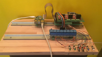
I have mounted Raspberry board, I/Os boards and rele board an plastic supports. These was arranged with DIN rail hangs so they are finnaly mounted on two DIN rail.

Now DIN rail are placed on a wood support in order to have an easy equipment for testing. In the final deployment they will be placed in the observatory frame. 


A temporary panel with push buttons is attached the the system. These are for symulation of buttons and sensors in obervatory. In this way is easy develop and test the application. 


Now is only matter of software. 


The developping of the application is alreay started, I hope to be ready in one week.


Tuesday, January 12, 2021

Step motor board

Hello to all,

 In the time from last post I have designed an realized the board for step motor driving.


Three step motors need to be driver by the controller in order to act as focuser. For step motor adapting an L298 bridge is chosen. From the market is possible found chip board with this component and radiator.


 Every board need 5 digital output for driving: Enable, IN1 (A phase +), IN2 (A phase -), IN3 (B phase +), IN4 (B phase -). It is not mandatory have the possibility to move all focus at the same time so phase signal can be common for all motor having maintaining one enable signal for each motor. In this way 3 enable signal plus 4 phase signal are needed.

No more digital output are available directly on raspberry board so the solution for increase its number is the use of a little board with the component PCF8574. It is a remote 8-Bit I/O Expander for I2C Bus


Because of step motor power signal can generate noise in the low power CPU signal is a good solution make outputs optoisolated.


This is the board schematic available also as external file 


This Board is designed so to be mounted up the I/O board. Mounting is shifted so to allow the plug and unplug of the connettors from I/O board and Raspberry and from I/O board and relè board


Thursday, December 17, 2020

IO Baord

Raspberry has 17 GPIO pins able to be programmed as input or output so these can be used as digital I/Os. They manage segnals with few Volts with the same electric potential of Raspberry, it is not a good idea have a long wiring with these signals, the risk is for the incoming noise and electric spike, they could hung up the Raspberry CPU.

For this purpose an expansion board need to be developed where 8 digital signal 24Vcc are optoisolated and adapted to the Raspberry GPIOs voltage and 8 Raspberry digital outputs drives relès. Relés make outputs optoisolated so driven signals can go far way from Raspberry.


For each digital input a this circuit is implemented


For digital output we bought a board from the market suitable for interfacing with Raspberry. Unfortunately this board reveses the commands from Raspberry, this not acceptable because during the Raspberry boot up for a litte time all reles are on. For this reason on the board an 8 inverter ports (74LS240) is applied in order to have the correct driving condition.


An analog input is needed in order to get the current observatory temperature. We bought an I2C analog to digital converter ADS1015. This is able to get 4 single ended signal or 2 differential signal. We select the second option in order to connect one PT100 termoresistor, this assure e low noise signal. This is the only not optioisalted signal so ti can’t go much far away from controller. A trimmable resistance che adjust the current flowing in the PT100 so to have precise measure.


An I2C FRam memory is mounted allowing the controller to save information need to be retained when power down. It has 32Kbyte more than enough.


In the resource the full board schematic is available


Wednesday, November 18, 2020

Don't forget something

As Alex Osborn said: "ideas evaporate faster than water". I think is better fix all the steps and project decisions in a document so it is possible review them in a long time.

Now in the resource gadget on this page you can find a link to that document. Now it is incomplete but I want update it along this project so at the end it can be use for reproduce and fix it .


Saturday, November 14, 2020

Motors are running !


We realized an application for test driver and motors on bench. As you can see wiring is rather confused... but is only temporary for test.

you can find here the Codesys application for this test:
 

In order to reach this result driverd


need to be parametrized for the specific motor and application. This is dome using the Infranor software “Gem Drive Studio”. It can be downloaded from Infranor website.

Voltage level are left as default, external breaking resistor in not needed

We selected the motor model we have, all parameters are set automatically

Auto phasing was asked, this activated a procedure for sensor phasing.


Position loop is set for minimum following error this is the best for this application.

Autotuning procedure was asked, this activated a strong step movement for loop gain computing. This procedure will ‘be done again when motors will be mounted on the telescope with real mechanical charge.


These are computed control parameters from autotuning procedure


Position sensor parameters are left as default.

This assure the position accuracy 360/4096 = 0.087 °


All other parameters are left as default.


Saturday, November 7, 2020

Raspeberry activation

Hello to all, 

work is in progress on the controller side.

We select Raspberry Pi 4 Model B as controller for the observatory. It is a medium performance controller and low prices, has a Linux operating system and is supported by Codesys. Many hardware peripherals are available on the market for Raspberry. CODESYS is the leading manufacturer-independent IEC 61131-3 automation software for engineering control systems. This provides us Ethercat fieldbus support, sophisticated motion libraries and communication libraries over IP. It is used for the brushless driving with DS402 profile.

Wifi connection is use for the communication with PC where Polypus is installed. Morover Raspberry has many GPIO lines useful for digital I/O connection and I2C line where many more complex devices can be manged.


For Raspberry OS installation the Raspberry Pi imager is used. It can be download from the official Raspberry website, it allows the OS selection. We used the raccomanded 


For Raspberry OS installation the Raspberry Pi imager is used. It can be download from the official Raspberry website, it allows the OS selection. We used the raccomanded

With this step the SD card is programmed ready to be inserted in the Raspberry board.

After that connecting Raspberry to: a video monitor, a USB keyboard and a USB mouse we have our own system running.

Other steps needs to be done in order to complete installation:

  1. Insert pasword for pi user.
  2. Connect wifi
  3. Enable SSH protocol.


Now you have Raspberry with standard linux support. For application where the real time is important jiitter genarate by task context switch need to be reduced. For this porpose a stronger kernel have to be installed. It can be found at following address with the info for installation.

 https://www.raspberrypi.org/forums/viewtopic.php?t=250927 


On this Linux system we install the Codesys runtime for Raspberry. First step is the Codesys developing system (IDE) on a PC. Main purpose of this software is the application developping. It can be dowloaded for free with this link:

https://store.codesys.com/tag/product/list/tagId/38/


After download ad installation we have the environment running


For Raspberry runtime installation and programming an extra package need to be get from Codesys website from this address


https://store.codesys.com/codesys-control-for-raspberry-pi-sl.html


This package is not for free but without license it is possible use it in demo mode for 30 minutes after that it is automatically stopped. This is enough for developping and evaluation.

Package needs to be installed in the codesys with menu command: tools/Package manager.

After package installation with the command: tools/ Update Raspberry Pi we have this panel. Selecting Raspberry IP address, giving the password for pi user you set in the OS installation and pressing “Install” button you have codesys runtime on our own device.


Now Raspberry is ready to accept Codesys application.

In the next day we'll delevop a test application for motion movement ..